![[OT] Investigating Can Bus I](https://github.com/Yuma-Tsushima07/blog-imgs/blob/main/investigating_cb-1/Investigating_CAN_Bus_I_Thumbnail.png?raw=true)
Intro
The first time I even heard about what OT was, when I met my former manager in the 1st few days of work, they asked me “What do you think OT stands for?”. I actually stumbled upon this question, however I did watch some YT videos upon “interview questions” this one did come up. I replied, I kinda dunno sorry… They told me the answer, “Operational Technology” and then I just left that topic in the dark.
Suddenly, it came up again, truthfully I did not know this was coming from the start. It was the main focus, or what I call it the wildcard. Sometime ago I was in a meeting with a person who just sparked interest in this field. I am not going to identify who this person is, but you know who you are! - Thank you btw
I could see this person had a passion towards the OT space and they would share some pointers to guide me in the right direction. Using the information, I got inspired to make this resource, not just for the team - but for everyone :D
Too Long Didn’t Read (TLDR);
- Someone asked me what OT was. I did not know really. Another person sparked a cog in my brain to research into this field.
What is CAN Bus?
CAN stands for Controller Area Network, which serves as a standardised method for enabling communication between microcontrollers and various devices independently of a host computer. What sets the CAN protocol apart from other communication protocols is its utilisation of a broadcast-type bus. This multi-master serial communication bus is characterised by a fundamental design specification emphasising high speed, robust noise immunity, and error-detection capabilities.
CAN Bus protocol facilitates data communication at speeds of up to 1 Mbit/sec, and its incorporation of features like Error Confinement and Error Detection enhances its reliability, particularly in noise-sensitive environments. This is particularly relevant in industries such as automotive manufacturing.
CAN is Broadcast
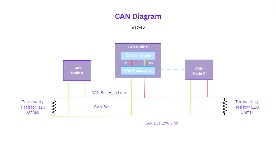
In contrast to conventional networks like USB or Ethernet, CAN operates differently by not transmitting large blocks of data point-to-point from node A to node B under the control of a central bus master. Instead, in a CAN network, brief messages are broadcast to the entire network, ensuring uniform data consistency across every node within the system.
-
All devices can hear the transmission
-
There is no way to send a data specifically to a node by its address or something
-
All nodes will pick up the traffic on the bus
-
CAN Controller: CAN controller deals with the communication functions described by the CAN protocol. It also triggers the transmission, or the reception of the CAN messages.
-
CAN Transceiver: CAN transceiver is responsible for the transmission or the reception of the data on the CAN bus. It converts the data signal into the stream of data collected from the CAN bus that the CAN controller can understand.
CAN Signals
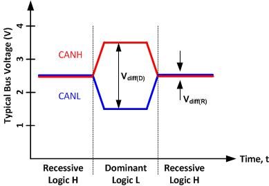
CAN achieves its robust noise immunity and fault tolerance through a differential signaling approach.
Differential signaling
When information travels through just one wire, interference from nearby electrical signals can mess with it. This interference might change the signal in a way that it’s not read correctly.
This method involves sending an electrical signal using two wires arranged as a differential pair. These wires can be part of a twisted-pair or ribbon cable, or they can be traces on a printed circuit board. Electrically, the two conductors carry voltage signals which are equal in magnitude, but of opposite polarity. The receiving circuit responds to the difference between the two signals, which results in a signal with a magnitude twice as large.
Balanced differential signaling, used in twisted-pair cables, minimizes noise interference and enables high signaling speeds.
Balanced
The term “Balanced” refers to equal and opposite currents in each signal line, creating a field-cancelling effect that significantly reduces the emission of unwanted noise.
CAN Characteristics
In contrast to conventional networks like USB or Ethernet, CAN operates differently by not transmitting large blocks of data point-to-point from node A to node B under the control of a central bus master. Instead, in a CAN network, brief messages are broadcasted to the entire network, ensuring uniform data consistency across every node within the system.
Standard vs Extended?
Originally Bosch released CAN specification CAN 2.0 for passenger Vehicles which explains 11- bit identifier frame architecture but later on it divided into CAN 2.0(A) which is named as standard CAN be used in passenger cars dealing with 11-bit Identifier while other is CAN2.0(B) which is known as extended CAN be used in heavy vehicles like Buses and Trucks it deals with 29-bit Identifier. So the basic difference in both standard at message Identifier field.
- 2.0B controllers are completely backward compatible with 2.0A controllers and can transmit and receive messages in either format.
- 2.0A controller based devices are capable of transmitting and receiving only messages in 2.0A format (standard format). With this type of controller, reception of any 2.0B message will flag an error.
Standard CAN
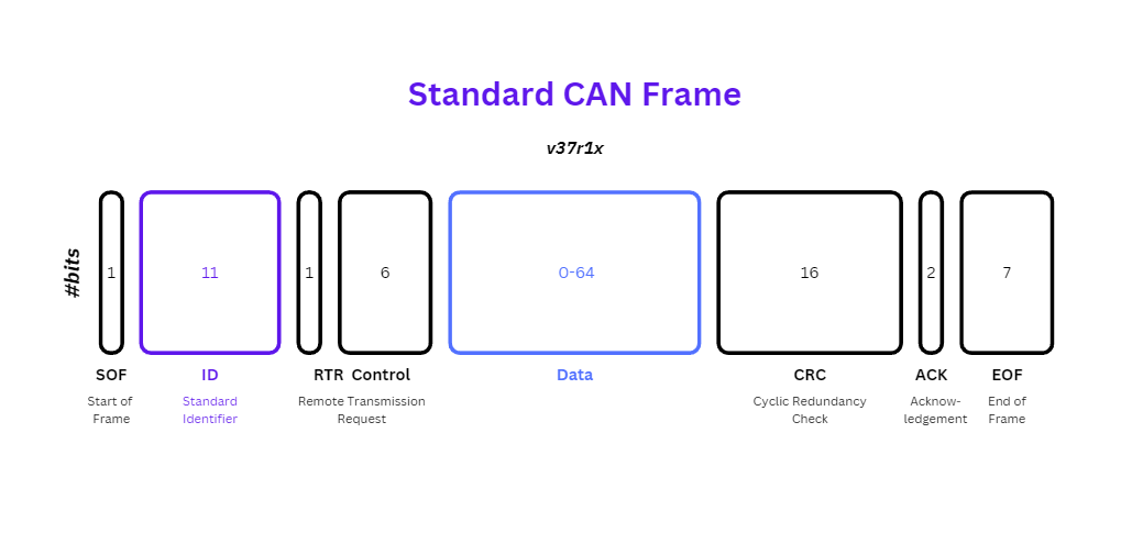
- SOF: The Start of Frame is a ‘dominant 0’ to tell the other nodes that a CAN node intends to talk
- ID: The ID is the frame identifier - lower values have higher priority
- RTR: The Remote Transmission Request indicates whether a node sends data or requests dedicated data from another node
- Control: The Control contains the Identifier Extension Bit (IDE) which is a ‘dominant 0’ for 11-bit. It also contains the 4 bit Data Length Code (DLC) that specifies the length of the data bytes to be transmitted (0 to 8 bytes)
- Data: The Data contains the data bytes aka payload, which includes CAN signals that can be extracted and decoded for information
- CRC: The Cyclic Redundancy Check is used to ensure data integrity
- ACK: The ACK slot indicates if the node has acknowledged and received the data correctly
- EOF: The EOF marks the end of the CAN frame
Extended CAN
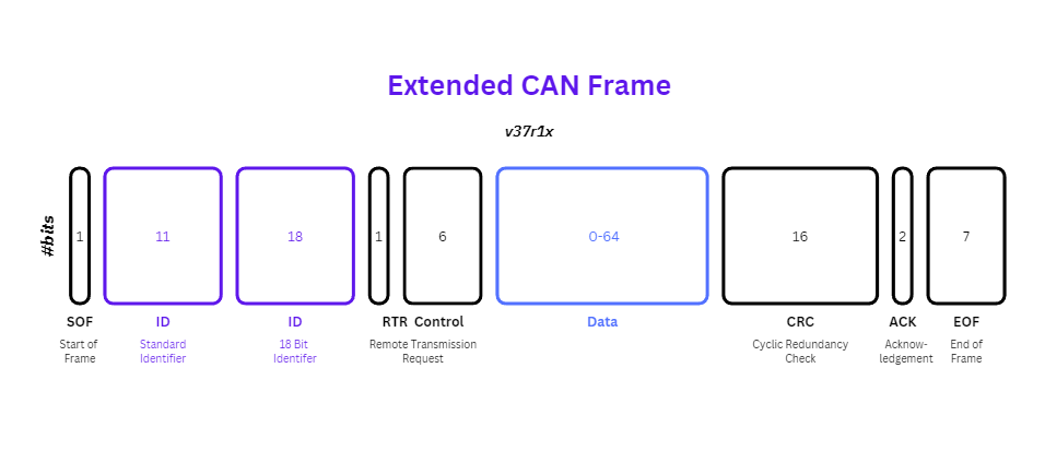
- SOF: The Start of Frame in Extended CAN begins with a ‘dominant 0’ bit, signaling the start of a frame transmission.
- ID: The ID field in Extended CAN includes an extended identifier, allowing for up to 29-bit identifiers. Lower values still have higher priority, similar to standard CAN.
- RTR: This field indicates whether the frame is a data frame (RTR = 0) or a remote frame (RTR = 1), where a node requests specific data from another node.
- Control: The Control field in Extended CAN includes the Identifier Extension Bit (IDE), which is ‘dominant 0’ for 11-bit identifiers and ‘recessive 1’ for 29-bit identifiers. It also contains the Data Length Code (DLC), a 4-bit value specifying the length of the data payload (0 to 64 bytes in CAN FD).
- Data: The Data field in Extended CAN carries the actual payload, containing up to 64 bytes of data. This payload typically includes CAN signals used for various applications.
- CRC: The CRC field is used to ensure data integrity in Extended CAN frames, just like in standard CAN. The CRC is computed by the transmitter and checked by the receiver.
- ACK: The ACK slot in Extended CAN indicates whether the message was acknowledged by the receiving node. A ‘recessive’ bit in this slot confirms successful reception.
- EOF: The EOF field marks the end of the CAN frame transmission, completing the data transfer process.
What is CAN Arbitration?
Since a serial communication system such as CAN is based on a two-wire connection between nodes in the network, all nodes are sharing the same physical communication bus, a method of data collision avoidance is mandatory to assure a safe data transfer.
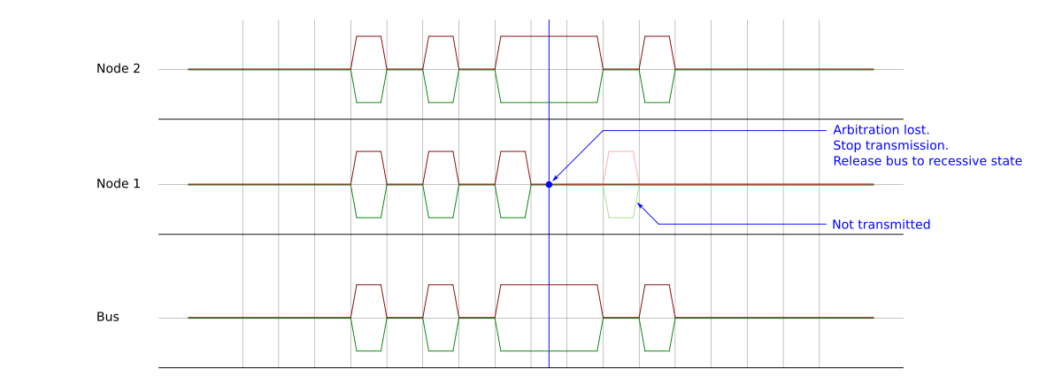
The bus is always in the recessive state by default (i.e. using pull up resistors), so when a node has to transmit one it leaves the bus in default state and when it has to transmit zero it drive the bus to dominant state.
Types of CAN Message Frames
Data Frame
The data frame is the most common message type, and comprises the Arbitration Field, the Data Field, the CRC Field, and the Acknowledgment Field. A Node uses this frame to send a message to other nodes on the Can bus.
Remote Frame
A node that requires data from another node on the network can request a transmission by sending a Remote Frame.
Error Frame
It is transmitted when a node detects an error in a message, and causes all other nodes in the network to send an error frame as well. The original transmitter then automatically retransmits the message
Overload Frame
It is similar to the error frame with regard to the format, and it is transmitted by a node that becomes too busy. It is primarily used to provide for an extra delay between messages.
Error Checking
The Controller Area Network (CAN) protocol employs comprehensive error detection mechanisms across different levels to ensure reliable communication. At the message level, cyclic redundancy checks (CRC) are used, where the transmitter computes a 15-bit CRC from the message content and each receiver recalculates it to compare against the transmitted value, flagging errors if discrepancies occur. Frame checks further enhance error detection by identifying invalid bits in critical frame components like CRC delimiters, ACK delimiters, End of Frame (EOF), or interframe spaces.
Bit-level checks involve continuous monitoring and bit-stuffing to maintain data integrity throughout transmission. Additionally, acknowledgment checks confirm message reception; each receiving node writes an ACK bit that the transmitting node reads to verify successful message delivery. If a message remains unacknowledged, an ACK error is triggered. These comprehensive error detection mechanisms collectively contribute to the robustness and reliability of the CAN protocol in industrial and automotive applications.
Summary
The Controller Area Network (CAN) protocol is a standardised method for communication between microcontrollers and devices, operating on a broadcast-type bus that ensures all nodes in the network receive transmitted messages.
CAN facilitates high-speed, robust communication with strong noise immunity and error-detection capabilities, making it ideal for automotive and industrial applications. CAN messages are broadcasted to all nodes, promoting data consistency across the network. The protocol uses differential signaling, where signals are transmitted via a pair of wires to minimise interference.
CAN supports both standard (CAN 2.0A) and extended (CAN 2.0B) formats, differing mainly in message identifier length. Standard CAN frames use 11-bit identifiers, while extended CAN frames allow up to 29-bit identifiers. Each frame consists of components like Start of Frame (SOF), Identifier (ID), Remote Transmission Request (RTR), Control (including Identifier Extension Bit and Data Length Code), Data, CRC (Cyclic Redundancy Check), ACK (Acknowledgment), and End of Frame (EOF).
Error checking in CAN involves cyclic redundancy checks at the message level, frame checks for component integrity, continuous bit monitoring, and acknowledgment to confirm successful message delivery. These error detection mechanisms ensure the reliability and integrity of data transmission in CAN networks.
End Note
This was my first blog post I made for this learning series. I enjoyed researching about this topic, as well as talking to people about this, letting people QA my article. Thanks to Artex, Raul and ARZ. I hope you liked reading this and found it insightful. If you do wish to see more feel free to contact me here!
References
Credits
(In no particular order)
- art/artex
- (ARZ101) Abdullah Rizwan - github, X, linkedin
- (unavailable07) Raul Cicos - gitbook, linkedin
Thanks all for QAing my blog post!